Skybolt Hints
Order Numbers
The Skybolt RV cowl kits consists of a few different parts:
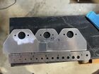
- The flanges (PN SK-RVFS1), which attach to an existing surface, and have a larger hole to attach the receptacle
- The receptacles (PN SK245A162A) which actually retain the studs when locked. These are adjustable in order to always make the studs look flush, and then locked in place by removing a pin on their side.
- A few SK245A161-INS receptacles (in addition to the many 162As mentioned above) which are smaller and can move more - these are meant for any holes don't line up so well and you can't get the stud to lock in place.
- The grommets (PN SK-OSG1-8), which sit on the outside surface to hold the stud and transfer the load onto the surface
- Rubber temporary retainers (PN SK-RET012) which are installed on the back side of the grommets but easily removable, meant to be used before painting so the grommets can be easily removed for painting. These are easily installed with your hands.
- Snap ring permanent retainers (PN SK-R4GS) which are metal rings installed on the back of the grommets to permanently hold them in place. They are meant to be installed with the SK-T26 tool (not included in the kit).
- The studs, which are the part visible from the outside which actually turns. These can be slotted (SK4002-2S) or Phillips (SK40S5-2S) (personal preference, but Phillips is more common). These are much easier to install with the SK-4P3 pliers.
- Standard AN426 rivets for all the above
- Some floating-element nutplates (MS21059L3), screws (MS24693-C272), Tinnerman washers (A3235SS020-24A / DP1085-20SS) for places where the Skybolts won't fit well
The different kits are then just different quantities of the above, plus a few installation helpers:
- 10 cleco inserts for locating / match drilling: SK-RVC
- 10 magnets for inserting into the cleco inserts
- 1 Drilling template for SK215/245: Template-215
- 1 Center hole Drilling template for SK215/245: Template-245
They do NOT include the SK-4P3 Pliers or SK-T26 tools, which must be ordered separately. The SK-4P3 pliers are needed to compress the spring while inserting studs through grommets, SK-T26 helps installing the final metal snap rings.
To select a kit, first decide if you want slotted (C1S) or Phillips (C1P) heads. Then decide which surfaces you want to attach with Skybolts:
- Firewall (top and bottom cowling) (-F) - quantity 36
- Upper firewall (top cowling) (-UF) - quantity 19
- Sides joining the two cowls (-S) - quantity 26
- Upper (upper firewall + side) (-U) - quantity 45
- Complete kit (no code) - quantity 62
The kit code will then be RV1014J + stud type (e.g. C1S) + surfaces (e.g. -F), like RV1014J-C1S-F.
Things to keep in mind when deciding whether to use Skybolts on the long side seam. Both solutions work, you just need to know the trade-offs.
- Skybolt studs don't fully retract. The cowl needs to be lifted off vertically or pried towards the outside to get it fully released. That works around the firewall however along the horizontal side seam, especially with the front 3 fasteners, the cowl is so stiff that prying it apart isn't easy. A workaround is to not use retainers on the backside of those grommets, so the entire stud with grommet comes out similar to screws.
- Using Skybolts all around the firewall already eliminates 6 of the 8 hinge pins. The two remaining ones on the sides are straight and easy to insert. The ends can be hidden nicely with this Aerosport RV-10 pin cover.
Gotchas
- Use the 3 1/2” or smaller spacing. If you use longer spacing you risk the cowl ballooning between them. You can cleco two of the SK-RVC locating helpers to a strip of aluminum 3.5" inches apart to quickly place the flanges at the right distance.
- Determine the necessary thickness of the shim that needs to be fabricated which goes underneath the flanges to make the cowling sit flush with the outer skin. Default is 20/1000".
- Consider countersinking the two rivet holes for each Skybolt cage on each flange before installing it on the aircraft. Caution: there is a right and wrong side to countersink; be sure you countersink the outward-facing side of the brackets (the side with the stamped Skybolt logo).
- Beware of the skybolt receptacles in the corners by the engine mounts; if you do not lay them out before hand, the mounts will interfere with those receptacles. Consider doing 46-02 Step 1 (temporarily installing the engine mount) before laying out your skybolt brackets. Then, do 46-02 Step 2 (removing the engine mount) to make it easier to rivet the skybolt brackets. If you missed this step, you can rivet the flanges by inserting a flat large screwdriver between the rivet and the engine mount as bucking bar and insert it further in as the rivet forms, or you can use structural blind rivets like the MK-319-BS.
- The skybolt flanges are wider than the stock hinges. For this reason, the skybolt flanges might interfere with the thicker portion of the cowling. Consider removing cowl material to make each flange fit and reinforce the area with a piece of fiberglass. See also this FB Thread (6/2025)You first install the flanges. The Skybolt logo is facing outward. Think ahead about how you will rivet the overlapping area as you will need to drill and dimple a hole should it fall into the overlapping area on the current flange before you install the next one.
- The receiver can be removed from the cage by pinching the retainer spring, then taking a screwdriver and getting it between the side wall and the spring, then prying it towards the center and up. The receiver then folds up and out. Inserting is done by getting one side engaged, then pinching the spring ends together and folding it down.
- Don't rivet the cage to the flanges with the two 4-4 rivers before you have located and match drilled the cowl itself with a 1/8 drill bit. This ensures, the magnet is as close to the cowl as possible. Riveting the cage is easier with the receiver removed. Otherwise, the squeezer my hit the receiver.
- The shop head of the 4-4 rivets locks down the receiver in its left/right movement. If you over-squeeze, the receiver won't fit, if you under-squeeze, the receiver will be floating a tiny bit.
- For locating the hole through the cowl, one can magnetize a steel pull rivet mandrill by clamping it between two of the supplied magnets, then removing the magnets, and hanging it off a string. Turn the needle around if the needle is repelled from the center of the hole. Consider using a 3D-printed or milled pin to mark up the outline of the 15/32" hole on the outside of the cowl, see the CAD section to get the files, see also this FB thread.
- The receiver has a pin that needs to be removed after setting the depth. It's convenient to have that pin on the side where you can reach more easily after final installation; "be certain to orient the antilock pins toward the outside (forward around the firewall; up along the sides) for access to the locking clip".
- The grommet needs to sit tight in the cowling. Don't use a 15/32" final size drill bit as it will not make a nice hole. Consider buying a suitable tapered reamer drill bit (15/32 is not common, so maybe a bit smaller, e.g. 7/16 which you probably already have for the door pin holes) then use a 15/32 reamer or step drill bit to carefully get to 15/32. If you are able to make a marker pin (see 9.), best is to use a Dremel bit and enlarge the pilot hole to just before the line, then do one run with the 15/32 reamer.
- The cleco adapters are used to find and start drilling the main holes where the grommets/studs will sit (with the help of magnets), but they're also usable as a sighting help when enlarging those holes to final size - by just inserting them into the flange hole mid-enlargement, you can tell if your hole is centered or not, and then "walk" the unibit (by applying lateral pressure as you spin it) to make it center properly. Check again every few steps of the unibit and you'll get very well-centered holes. This is when you can't get a marker pin (see 9.).
- If you install a BRS parachute, you need to not have a flange in the area where the strap comes in.
- If you make your own flanges, the center hole needs to be 0.6". If smaller, the rubber temporary grommet will get stuck and strip when removing the cowl. If larger (e.g. 0.625"), the hole distance to the two 4-4 rivets gets small.
- Don't make a continuous, wide metal strip in lieu of the individual flanges. The cowling is concave in two dimensions which a solid strip cannot adhere to, it would need a lot of fluting.
- When setting the depth, there are two actions involved: getting the stud engaged in its locking position and turning the entire threaded insert. You might have to hold against the insert first to get the stud to lock, then spin it. When removing the stud, you only want to disengage the stud from the locking position and come straight out, you don't want to touch the depth setting while you turn the stud. Since it's possible to lift the ring with an awl and correct the depth setting after pulling the pin, it is quite feasible to just set all receptacles to your best depth before installing. Some might need half a turn in one or the other direction later but it resolves the issue of the receptacle spinning accidentally before pulling the pin.
- The screws / nutplates are for "the nose area between the spinner air induction holes and on some cowlings the inside of the outer portion of the induction holes is a very stressed – high pressure area best suited for a solid clamp up screw. It is required that the builder fabricate .032-.040 backing plates to mount the nutplates used in the nose."
- You use the rubber rings to hold the grommets until the airplane gets painted, then switch to the permanent metal snap rings which are hard to remove, even with this tool. Consider using easy-to-remove snap rings from McMaster (see this part / pliers) instead of the rubber rings until painting. See also this FB thread.
- The two short sections on the bottom of the lower cowl are a high stress area (builders using piano hinges there report breakage of eyelets). Consider using 3 Skybolts instead of 2 on each side. This requires a sacrificial extra flange to make a shim.

Relevant links
- Skybolt web store
- Skybolt installation instructions for Vans airplanes
- Check out Andrew Gilroy's 14 part video series on mounting his RV-14 cowl YouTube
- Ryan Flys RV-7 installation video