SECTION 10: TAILCONE
Build Instruction Updates
- 10/05/21 10_10.pdf
Check for more recent updates here
Hints
- If you intend on installing a yaw damper as part of your autopilot package, you are encouraged to think about the mounting hardware for it while you are building the tailcone, as access is much easier NOW than later. See this page for more details: https://rv10.org/index.php?title=Yaw_Damper_Servo
- Vans also sells a mounting bracket that fits in the RV-10 tailcone (https://rv10.org/index.php?title=File:Screen_Shot_2022-03-24_at_11.50.50_AM.png) that is perfect for a spot to mount additional hardware. It's much easier to install earlier in the build process than later.
- The tie down ring and the jam nut is not included in the kit.
Consider those sources:
- Consider electrical wiring and rudder cables before completing the tailcone. It is much easier to do before the top skin is riveted than to climb inside later.
- Complete section 10 up to page 10-21 step 4. Do not rivet the Aft Deck assembly (F-1014) or the Top Skin (F-1075) until you are happy with the wiring.
- If you don't have the fuselage kit yet, you can purchase the rudder cables (F-1053) from Vans for about $110, then later have them deleted from the fuselage kit.
- Follow the instructions in section 38 (page 38-8) on how to install the rudder cables. Install the cables through F-1008, and coil them for later between F-1007 & F-1008.
- You will need to wire three (or more) systems:
- The tail light -- refer to OP-56 for instructions on how to route the wire to the rudder. If you have ZipTips (see Wing Tips), the tail light is optional.
- The trim motor and sensor.
- A coax for the VOR antenna -- route a 25ft coax with a male BNC connector to the base of the vertical stabilizer. 25 feet of cable allows an unbroken run all the way to the control panel; each connector results in a drop in signal strength, so the minimum should be used.
- (More to come.)
Preparation
Make sure you have enough clecos. During the initial assembly, I used about 650 clecos.
Page 10-2
Step 3 - Consider also using the center line on the back of the AEX tie down as an additional reference to center the AEX to the centerline of the F-1012A bulkhead. It can be difficult to accurately center the marked lines in the exact centers of the holes as referenced in the plans.
- 5/28/22 I did it per the plans, drawing the two lines exactly. Now use a cleco CLAMP on the bottom (threaded end) and a wood C clamp on the top gently holding it in place while you drill the 4 holes. A little confusing in the plans it calls to drill the 3/32 out w/ a # 30 drill. Correct. It's a 3/32 hole oversize it to #30 so it will receive a -4 (4/32) rivet down line. See page 10-18 for rivet size. Drill the 4 #30 holes first and cleco as you go. Then drill the 3/16 holes also clecoing if you have 3/16 clecos.
Tie down assembly
Step 1: 5/28/22 Taping the Tie down. Note: The hole should first be drilled out to 5/16 to receive a 3/8-16 tap. The hole is undersized by Vans. A trick a machinist taught me, put the tap in your drill press and center your piece under while turning the tap BY HAND. DON'T turn on the drill! It's just a jig to keep things straight while you start the tap. Once you get a couple turns on the tap, take it out, put in your vice and finish.
Tap drilling
Step 5: Those nut plates will be used to hold the rudder cable sleeves with the help of an Adel clamp. It is then very difficult to start the AN3-4 bolt into those nut plates because the area is very hard to reach. Now is a good time to test run the bolts.
Page 10-4
Step 1 - Double check the length and make sure you center the F-1010A on the F-1010 bulkhead to avoid any edge distance issues later on when match drilling the top deck to the longerons.
Page 10-5
- Step 1 The angle in figure one is shown upside down in regards to its later mounting position. The angle has a vertical part that gets trimmed 5/32 on both sides and it has a forward pointing horizontal part that gets wider towards the front where it reaches the full width of 10 3/4.
- Step 4 Consider making a jig to make drawing the center line more consistent and efficient. YouTube video: https://youtu.be/yC1kzDO_Gg8?t=590
- Step 4 Carpenters Scribe modified for a sharpie. Drill 3/8 hole in end. Keep it parallel. Works great easy to make. See image:
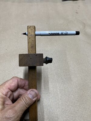
Carpenters Scribe Modified for sharpie

- When cutting the stiffeners to length, consider making them slightly longer than Vans recommends in the instructions by approx 1/8 inch. If cut too short, you may end up with edge distance issues when match drilling the end rivet holes. The length can then be adjusted if desired after first fit up.
- Don't assume the stiffeners are exactly 8 foot long and just measure how much to cut off, measure across the entire length to mark the cut-off line.
Page 10-8
- Step 1: For hints, see this VAF thread
Page 10-8
I had to buy a large clamp that could fit across the width of the F-1014 aft deck in order to align the longerons correctly.
Page 10-13
There is a service bulletin (https://www.vansaircraft.com/wp-content/uploads/2018/03/sb18-03-30.pdf ) for the elevator stop (F-1012D). As mentioned in this YouTube build video (https://youtu.be/g5ONB4e28TI ), Van's did send the required material to create the new part with the rest of the kit (subkit #5), but did not update the plans to reflect the service bulletin.
Page 10-15
Step 7 instructions only apply to the web of the F-1012B Bulkhead. Dimpling of the flanges of this part is done in step 4 on page 10-16 which instructs to not dimple the topmost hole.

Page 10-20
If working alone, you can get away with riveting the bottom skin stiffeners to the bottom skin before clecoing the side skins on -- and you can back-rivet these.
Step 2 - If you plan to install the BRS parachute, don't rivet the forward 2 holes of the F-1047F-L/R stiffeners as the rear attachment external plate is using same rivet holes.
Step 7 - The outer rivets are very hard to get to. Plans call for AN470AD4-4 rivets, but you may consider using CR3213-4-2 CherryMax rivets (confirmed with builder support that this should be okay). Measure your parts to ensure proper rivet length. You may have to modify your hand riveter to fit within the opening. YouTube video: https://youtu.be/cvwDYFGeK6s?t=614
Step 7 - Alternatively, you can rivet the stiffeners to the rudder stop brace before inserting the F-1012 assembly in for final riveting.
Page 10-21
Step 4 - If you plan to install additional air intakes for ventilation (e.g. an overhead console with air vents), you should purchase additional NACA vents from Van's (part SV-1) or at least find a good template and consider cutting the holes for these prior to riveting the side skins on to the tailcone.
Step 5 - If you already have the rudder cables, consider installing them along with rudder fairings (optional) at this point before riveting the aft deck. See Rudder_Cable_Fairings.
Page 10-23
Step 2 -- before Cleco'ing the aft top skin, check out the last step of this section -- Page 10-24 Step 3. I think this would be a lot easier to do before installing the aft top skin if you can still rivet with it in place. I had to crawl in the tailcone to do this step at the end.
Step 4 - Check whether the AN3-5A bolts to hold down the Bell Crank Angles are in fact the proper bolts. Builders are reporting that those are too long. Note: In general, no more than 3 washers can be stacked to compensate for too long bolts.
Step 5 - If you are going to install pitch and/or yaw autopilot servos, you may want to order those parts and figure it out before you get too far along in this section. It can also be done later, but it feels like a good time to do it to me.
The entire F-1035 top plate needs to come off later when you thread in the two push-rods through this opening. Don't mount the servos yet, just the yaw damper servo bracket.