BRS Installation Hints
Builder Logs
Additional Parts Needed
- The 8-32 X 5/8” screws (position 42 and 50) are questionable (soft material), consider ordering Spruce part no Part# AN526-832R10-50 Pack of 50.
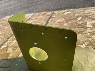
Top Rear Attachment Gussets
- If you position the gussets, check whether they potentially sit against clecos and aren't tucked in completely. If you install the parachute during the construction of the RV-10, the tailcone upper skin is still not riveted. Those rivets will sit against the outside of the bend in the upper gusset. Evaluate how much room will be needed for the dimples / shop heads.
- The manual asks for a 7.5 inch distance between the center of the gussets. Being that close is really not easily achievable and the photos in the manual don't comply.
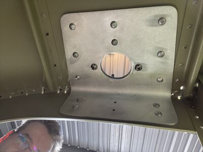
- On the right side, the gusset needs to anyway sit further to the outside because of the vertical baggage bulkhead channel (F-1028). The gusset therefore overlaps the outside J-stiffener (F-1047) and you actually need to maximize the overlap to have proper edge distance for the rivet holes that go through the gusset. It also requires to make the gusset thinner where the stiffener overlaps. The overlap can easily be marked after match drilling and bolt installment if the top skin is taken off. The rivet holes in the gusset need to be counter sunk as the stiffener is dimpled.
- If you locate the left angle bracket 7.5 inches center to center apart from the right one, the bracket overlaps the center J-stiffener at a slanted angle which doesn't work as some rivet holes will have bad edge distances. A compromise is to overlap the center stiffener just a tiny bit at the front. The center to center distance is then 8 5/8 inches. The gusset needs to be thinned to accommodate the short stiffener overlap.
Picture shows temporary fasteners installed inside out for convenience.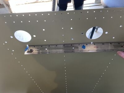
- The fastener holes need a #19 drill.
- The two larger 1/4 inch holes that need to be match drilled should be pre-drilled with a smaller diameter drill bit first using the 1/4 to 1/8 inch bushing which comes with the RV-10 kit.
- The big round hole of the angle bracket that needs to be match-drilled into the top skin has the size of a 1.5 inch conduit (actual hole size: 1.951 inches). Very easy to do with a hydraulic punch, e.g. at Amazon. Suitable should also be a bare punch set that uses a bolt instead of hydraulics, e.g. at Amazon.


Bottom Rear Attachment Bracket
- The manual says to avoid interference with the longitudinal stringers however, the brackets don't fit between them. The photos also show overlap. One needs to grind away a bit to allow space for the stringer.
- Note: the manual has photos of a different bottom rear attachment bracket. It has a square profile (which means it interferes with the shop heads). The current kit comes with a bent bottom bracket which leaves room for the shop heads but the holes moved higher up and now don't fit below the lighting hole.
- The distance of the centers of the brackets should be 15 inches. However that is not achievable. The center tunnel is 2.4 inches outside to outside wall. The bracket is 4.8 inches wide, so the gap between bracket and center tunnel should be 3.9 inches to give you 15 inches center to center (2.4 + 3.9 + 2.4 + 3.9 + 2.4). If you do that you are crossing the stiffener in the middle of the bracket. Doable is 0.5 inch which gives you 8.2 inches center distance (2.4 + 0.5 + 2.4 + 0.5 + 2.4). This is also what the photo shows in violation with the instructions. Best is to align the innermost hole with the rivet line that connects the F-1019-L inboard baggage rib with the F-1006B Bulkhead.
- The edge distance for the holes in the area of the lighting hole of the bulkhead is violated if used as shipped in the kit. One needs to move the outer bolt lower (a tiny bit into the bend; the bend needs to be ground flat for the screw head) and the 2nd outermost hole towards the center.
The lines represent the lighting hole inside diameter, the lighting hole diameter where it starts being flat and then 2xD edge distance to all edges.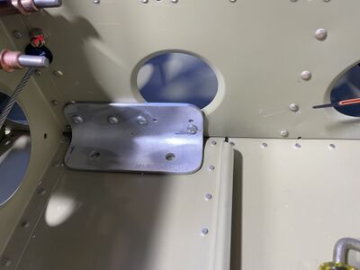
Note:Fasteners shown are temporary in all images.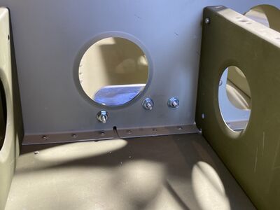
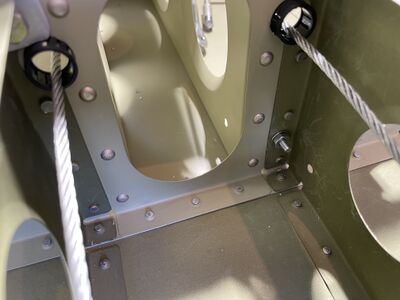
- On the inside top corner, the bracket interferes with a rivet in the bulkhead, one needs to make an indent.
- The 5/16 hole match drilling can be done using a 5/16 to 1/4 inch drill bushing or a short piece of aluminum tube with 5/16 OD and 1/4 ID. With it, drill a 1/4 inch hole from the inside to the outside using an angle drill attachment. Then use a unibit step drill and widen the hole from the underside of the fuselage from 1/4 to 5/16. Finally file a bit from the inside to ensure the hole matches all the way around the circumference.


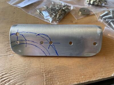
Rear Attachment External Plate
- Mark the centerline on the underside of the bottom skin. Mark the centerline on the external plate. Assess the fit and bend the plate until it conforms to the shape of the tailcone.
- Use duct tape to tape the bottom plate to the bottom skin.
- Match drill one of the 5/16 hole using a drill bushing and step drill bit as before and fasten the bottom plate using a bolt and nut.
- The manual doesn't specify where exactly to place the roughly 30 3/32 rivets. If you haven't left the rivets open during the tailcone build and tailcone attachment, one option is to drill out existing rivets, another is to make new holes in between existing rivets, slightly out of line but still keeping 3/16 stiffener edge distance. The minimum distance between rivets in a double row is 4 x diameter (3/8 for 3/32 rivets), see AC 43.13-1B, page 4-20. As the regular rivets are more than 1 inch apart, it isn't a problem to add another rivet at mid distance.
Rocket Support


Rocket Activation Handle
.jpg)

